Whether you're a product designer iterating on a housing prototype, a factory engineer printing assembly jigs, or a hobbyist building drone frames, fused deposition modeling delivers functional thermoplastic parts without the lead times or tooling costs of traditional manufacturing.
This guide covers everything you need to know - from how the process works and which materials to choose, to tuning parameters, comparing alternatives, and designing parts that actually perform.
Key Takeaways
- Fused deposition modeling (also called fused filament fabrication) is a material extrusion additive manufacturing process that builds parts by melting thermoplastic filament and depositing it layer by layer through a heated nozzle. FDM accounts for the largest installed base of 3D printers worldwide, making it the most accessible entry point into 3D printing.
- FDM 3D printing is the go-to technology for rapid prototyping, jigs and fixtures, and low volume production of end use parts thanks to its low cost, simple operation, and broad range of common materials including PLA, ABS, PETG, nylon, and carbon fiber composites.
- Print quality hinges on a small set of parameters - nozzle temperature, build plate temperature, layer height, and cooling - which together control layer adhesion, mechanical strength, and surface finish.
- FDM is ideal for small to medium production runs and complex geometries where injection molding would require expensive tooling, but it cannot match resin or powder-bed processes for ultra-fine detail or perfectly smooth surfaces.
- This article compares FDM to other additive manufacturing processes like SLA, SLS, MJF, and binder jetting, and provides practical best practices for choosing materials, tuning settings, and designing strong FDM parts.
What Is Fused Deposition Modeling (FDM)?
Fused deposition modeling is a 3D printing process that uses a continuous thermoplastic filament - typically 1.75 mm or 2.85 mm in diameter - fed through an extrusion head, melted, and deposited onto a build platform one layer at a time. As each new layer is deposited on top of the previous layer, the melted material fuses and solidifies, gradually building up the desired shape from bottom to top. FDM is a cost-effective and inexpensive process that supports a wide range of thermoplastic materials, from basic polylactic acid (PLA) to high-performance polymers like PEEK.
The term "fused deposition modeling" is a trademark owned by Stratasys, whose co-founder S. Scott Crump invented the process in 1988. The open-source community uses "fused filament fabrication" (FFF) to describe the same technology. Both terms refer to identical hardware and workflow.
FDM sits within the material extrusion category of additive manufacturing, distinct from vat photopolymerization (SLA, DLP), powder bed fusion (SLS, MJF), and binder jetting - each offering different tradeoffs in resolution, materials, and cost.
Modern FDM printers range from sub-£300 desktop units for hobbyists and education to industrial systems exceeding £100,000 used for aerospace tooling and certified end-use parts. This massive spread exists because:
- Key Stratasys patents expired around 2009, opening the door to open-source and consumer printers through projects like RepRap
- Component commoditization - inexpensive stepper motors, hotends, and open-source firmware - drove costs down dramatically
FDM is easy to use and ideal for beginners, which is why it became the dominant entry-level 3D printing technology worldwide.
How FDM 3D Printing Works
The FDM printing workflow starts with a 3D CAD model. The model is imported into slicer software, which divides it into horizontal layers and generates G-code - the machine instructions that tell the printer exactly where to move and how much filament to extrude. FDM requires the creation of a 3D model and conversion into these machine instructions before any printing begins.
Hardware Components
Every FDM printer shares the same core components:
- Filament spool and feed path - supplies raw thermoplastic filament to the extruder
- Extruder/drive gears - grip and push filament (direct-drive or Bowden tube)
- Hotend - heater block, thermistor, and nozzle that melt the filament
- Motion system - Cartesian gantry, CoreXY, or bed-slinging design
- Build plate - heated or unheated, often with PEI, glass, or textured surface
- Cooling fans - control how quickly the deposited material solidifies
The print head pushes filament into a heated nozzle where it melts slightly above the polymer's glass transition or melting point. The thin nozzle extrudes a bead of melted material that is pressed onto the previous layer, creating mechanical bonding through polymer chain diffusion. The extrusion head moves along X and Y toolpaths to complete one layer, then either the nozzle or the build plate shifts in Z so the next layer can begin. Successive layers build up until the part is complete.
Cooling fans play a critical role: they control how quickly each deposited strand solidifies, directly affecting overhang quality, bridging performance, and whether you see clean edges or drooping layer lines. Too much cooling weakens bonds between layers; too little causes sagging on overhangs.
Key Print Parameters for FDM Printers
Tuning a small set of core parameters largely determines strength, dimensional accuracy, and surface finish. FDM supports a wide range of thermoplastic materials, and each demands different settings.
- Nozzle temperature: Controls melt viscosity and layer bonding; typical range 190–280 °C (higher for nylon).
- Bed temperature: Affects first-layer adhesion and warping; ranges from 50–110 °C depending on material.
- Print speed: Influences cooling time and accuracy; usually between 30–1000 mm/s.
- Layer height: Determines surface quality and print time; commonly 0.20–0.30 mm (200–300 microns).
- Extrusion multiplier: Adjusts over- or under-extrusion; typical range 0.90–1.10.
- Cooling fan speed: Impacts overhang quality and bonding; varies from 0–100%.
- Retraction: Controls stringing; typical distances are 0.5–6 mm.
Common nozzle temperature ranges by material: PLA at 190–220 °C with bed at 50–60 °C, ABS at 240–260 °C with bed at 90–110 °C, and PETG at 230–260 °C with bed at 70–80 °C. Layer height in FDM commonly ranges from 120 to 300 microns - thinner layers improve surface finish and fine detail but significantly increase print time, while thicker layers speed things up at the cost of visible stair-stepping.
Typical desktop FDM build volumes are around 200 × 200 × 200 mm (some reaching 300 × 300 × 330 mm), while industrial systems like the BigRep PRO offer build envelopes up to roughly 1,000 × 1,000 × 1,000 mm for large tooling or fixtures.
Desktop vs. Industrial FDM Printers
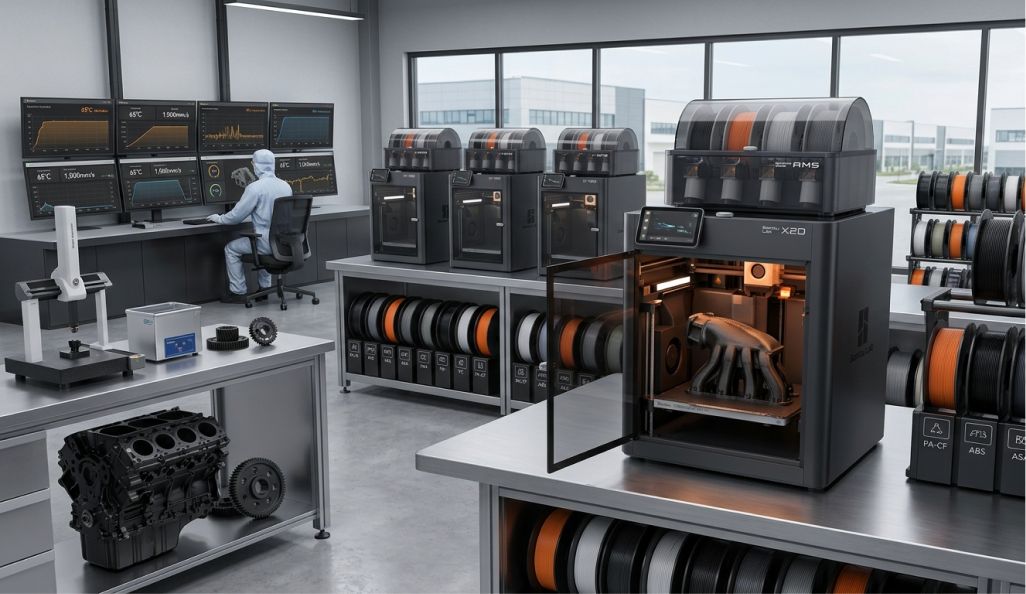
Desktop FDM printers are optimised for low cost and flexibility, while industrial systems focus on reliability, repeatability, and engineering-grade performance. FDM is scalable from desktop units to industrial machines, and the right choice depends on your application.
Desktop advantages:
- Purchase cost often under £1,000
- Open material choices from dozens of filament suppliers
- Ideal for makerspaces, education, and iterative prototyping
- More manual calibration and maintenance required
- Typical tolerances around ±0.5 mm
Industrial advantages:
- Controlled build environments with enclosed, heated chamber and filtered air
- Support for advanced thermoplastic materials like PEI (ULTEM), PEEK, PPSU, and carbon fiber reinforced nylon
- Traceable process control and material certifications for aerospace, automotive, and medical applications
For industrial use, companies like East/West Industries achieved 80% cost reduction and 87% time savings by switching from metal dies to Nylon 12CF composite dies printed on a Stratasys 450mc. When evaluating desktop versus industrial FDM technology, consider annual part volume, required accuracy, and whether your application demands certification or quality documentation.
Technical Characteristics of Fused Deposition Modeling
FDM printed parts have distinct mechanical and visual characteristics tied to their layer-by-layer construction. Understanding these characteristics is essential for designing parts that perform reliably.
Anisotropy: Parts are strongest along the filament deposition direction in the x y plane and weakest between layers in the z direction. This makes orientation and layer adhesion critical for load-bearing applications. Mechanical strengths in the z direction are weaker in FDM parts because interlayer bonds rely on polymer chain diffusion rather than continuous material flow.
Surface quality: FDM typically produces visible layer lines on printed parts. These can be reduced with smaller layer heights, optimised cooling, and post-processing such as sanding or vapour smoothing, but they are inherent to fused deposition.
Dimensional accuracy: Well-tuned desktop printers achieve roughly ±0.2 mm or ±0.5% of nominal dimensions. Industrial systems can do better with proper calibration.
Internal structures: Infill patterns (grid, gyroid, honeycomb) and shell thickness let engineers balance strength, weight, and material usage - a design freedom that differentiates FDM 3D printing from solid injection-molded plastics.
Warping and Dimensional Stability
Uneven cooling and internal stresses cause corners to lift from the build plate, particularly in semi-crystalline plastics like ABS and nylon. FDM struggles with overhangs steeper than 45 degrees, and large flat areas are especially prone to warping.
Strategies to reduce warping:
- Use a heated build plate and a heated chamber
- Apply brim or raft adhesion features
- Round sharp corners and add fillets
- Avoid large solid flat sections
PLA and PETG are less prone to warping and recommended for beginners. ABS, PA (nylon), and PC typically require temperature-controlled environments. For example, an ABS automotive bracket printed in a 60–70 °C chamber shows significantly better dimensional stability than one printed on an open-frame machine at room temperature - warping is reduced dramatically, and layer cracking is nearly eliminated.
Layer Adhesion and Mechanical Strength
Layer adhesion is governed by interlayer diffusion of molten polymer chains. When the material cools too quickly, or the nozzle temperature is too low, insufficient chain entanglement occurs across the interface. Excessive fan cooling compounds this problem, producing brittle parts that fail along layer lines under tensile or bending loads.
To improve interlayer strength:
- Use slightly higher nozzle temperatures within material limits
- Reduce fan speeds for engineering materials like ABS and nylon
- Print thicker perimeters (shells) - 2–3× nozzle diameter is a good baseline
- Orient parts so critical loads run in the stronger XY directions, not the Z direction
Post-print annealing in a temperature-controlled oven can increase crystallinity and strength for materials like PLA, PETG, or certain nylons, though there is some risk of distortion if the part is not properly supported.
Support Structures, Overhangs, and Infill
Fused deposition modeling cannot print into thin air beyond certain angles, so slicer-generated supports are often required. Overhangs up to about 45° from vertical usually print without support material. Steeper angles and long bridges generally need supports.
Supports can be printed in the same filament and manually removed, or in a soluble support material (PVA, BVOH) on dual-extruder systems for more complex deposition modeling geometries. Removing support structures from FDM parts can be tedious and leave marks, which is why support removal strategy should be part of your design process.
Infill guidelines:
- 10–20% for cosmetic models and visual prototypes
- 30–50% for functional prototypes and moderate-load parts
- 50%+ or solid regions for high-load features
Shell thickness and infill pattern interact to determine bending stiffness - thicker shells contribute more to rigidity than infill alone in most beam-like geometries.
Common Materials for FDM 3D Printing
Fused deposition relies mainly on thermoplastic polymers supplied as filament. FDM printers support a broad range of polymers and composite materials, and choosing the right one is often the most important decision in a project. Common FDM materials include PLA, ABS, PETG, and TPU.
- PLA Nozzle Temp: 190–220 °C Bed Temp: 50–60 °C Key Properties: Biodegradable, easy to print, low heat resistance
- PETG Nozzle Temp: 230–260 °C Bed Temp: 70–80 °C Key Properties: Tough, chemical resistant, moderate heat tolerance
- ABS Nozzle Temp: 240–260 °C Bed Temp: 90–110 °C Key Properties: Higher strength and thermal stability, warping prone
- ASA Nozzle Temp: 240–260 °C Bed Temp: 90–110 °C Key Properties: UV resistant, suitable for outdoor use
- TPU Nozzle Temp: 200–240 °C Bed Temp: 30–60 °C Key Properties: Flexible, vibration damping
- Nylon (PA) Nozzle Temp: 250–280 °C Bed Temp: 80–110 °C Key Properties: Impact resistant, hygroscopic
- PC Nozzle Temp: 260–300 °C Bed Temp: 100–110 °C Key Properties: High heat deflection, strong
PLA is biodegradable and easy to print with, making it ideal for visual models. ABS offers higher strength and thermal stability than PLA.
PETG - based on polyethylene terephthalate glycol - combines ease of printing with mechanical properties similar to ABS.
Engineering materials for FDM include nylon and polycarbonate for demanding applications. For flexible parts like gaskets and vibration-damping mounts, TPU requires slower speeds and typically a direct-drive extruder.
Composite and speciality filaments such as carbon fiber or glass-fiber-reinforced nylon dramatically increase stiffness but require hardened nozzles due to abrasiveness. Research published by the European Ceramic Society has also explored FDM for ceramics, where ceramic powder is suspended in a thermoplastic binder, extruded, and then sintered to produce dense ceramic parts - expanding deposition modeling well beyond conventional polymers.
Applications of FDM Technology
FDM is commonly used for rapid prototyping, concept models, and functional parts. FDM technology is used in aerospace, automotive, and medical sectors, and its applications have expanded significantly since early industrial adoption in the 1990s. The shift from prototyping-only toward mixed usage accelerated between 2015–2025 as materials and printers matured.
Rapid Prototyping and Product Development
FDM enables overnight or same-day prototypes directly from CAD data, dramatically reducing time-to-feedback. FDM is widely used for rapid prototyping across industries, and the low material cost makes it ideal for iterative design where engineers print several variants on one build plate.
Fused filament fabrication is especially useful for form-and-fit models, snap-fit tests, and creating functional prototypes before committing to expensive tooling. Automotive interior trim samples printed in ABS, consumer product handles in PLA for ergonomic testing, and electronics housings in ASA are all routine examples. FDM offers fast turnaround for prototypes and low-volume production.
End Use Parts and Low-Volume Production
FDM produces durable end-use parts for low-volume production, especially where customisation or complex geometries are required. Examples include replacement machine guards in PETG, drone components in carbon fiber nylon, and patient-specific medical positioning aids.
United Launch Alliance reduced costs by 57% by consolidating roughly 140 separate environmental control duct components into about 16 FDM-printed ULTEM parts. This kind of part consolidation - creating durable parts with internal channels and lattice structures that would be impossible with traditional machining - is where this manufacturing process truly shines.
The economic crossover point where additive manufacturing becomes cheaper than injection molding typically falls at runs of tens to a few thousand pieces, where mold costs cannot be amortized.
Jigs, Fixtures, and Tooling
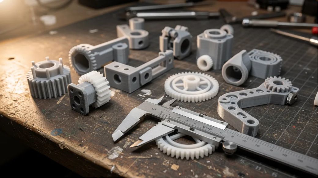
FDM is suitable for creating custom jigs and fixtures quickly. Shop floors use FDM printers to produce drill guides, assembly aids, inspection gauges, and ergonomic tooling overnight - then redesign and reprint them when engineering changes arrive. Materials like nylon-CF or PC provide the wear resistance needed for repeated use alongside traditional metal tooling.
Architectural, Educational, and Visual Models
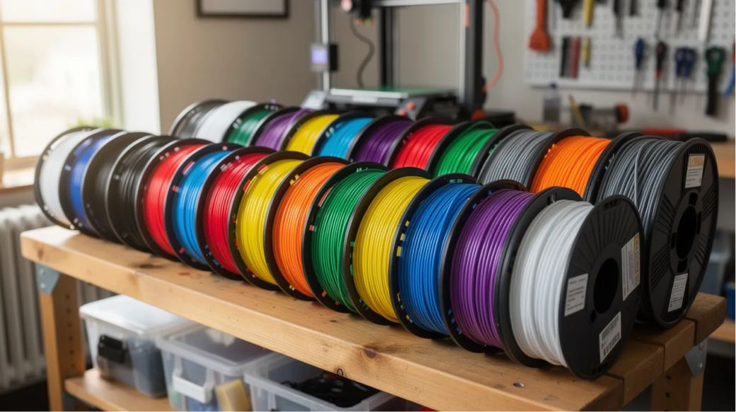
FDM can create architectural models for visualising complex structures, often printed in PLA for client presentations. Schools and universities use FDM technology to produce STEM teaching aids - molecular models, gear trains for disassembly exercises, and anatomical structures - making abstract concepts tangible. Brightly colored PLA or PETG filaments work well where ease of printing matters more than extreme mechanical performance.
FDM vs. Other 3D Printing and Traditional Processes
No single additive manufacturing method is universally best. The right choice depends on resolution needs, material requirements, volume, and budget.
- Resolution:FDM has lower resolution compared to SLA/DLP (excellent), SLS/MJF (good), binder jetting (good), and injection molding (excellent).
- Surface finish: FDM parts have visible layer lines, while SLA/DLP offers smooth finishes, SLS/MJF provides good surface quality, binder jetting moderate, and injection molding excellent.
- Materials: FDM uses thermoplastics and composites; SLA/DLP uses photopolymers; SLS/MJF primarily uses nylon and polyamide; binder jetting works with metals, sand, and ceramics; injection molding can use nearly any polymer.
- Supports needed: FDM requires supports for overhangs greater than 45°, SLA/DLP also requires supports, SLS/MJF and binder jetting do not need supports, and injection molding is mold-based (no supports).
- Cost per part (low volume): FDM has low cost per part, SLA/DLP and SLS/MJF have medium to medium-high costs, binder jetting is high, and injection molding costs are very high due to tooling.
- Best volume range: FDM is suitable for 1 to 5,000 parts, SLA/DLP for 1 to 500, SLS/MJF for 50 to 10,000, binder jetting for 100 to 100,000, and injection molding for volumes above 10,000.
SLA produces superior surface finishes and resolution compared to FDM, making it ideal for jewelry, dental models, and fine detail work. SLS offers better performance for functional and complex parts than FDM, producing more isotropic nylon parts without support structures. Binder jetting is a high-speed process for metal and sand parts but requires post-processing like sintering. FDM typically requires less post-processing than other techniques such as SLA, where uncured resin must be washed and UV-cured.
Advantages of FDM Technology
- Low entry cost - FDM is a cost-effective 3D printing technology with machines starting under £300
- Real thermoplastic materials enable realistic mechanical and thermal testing
- Scalable from single desktop units to large printer farms for higher throughput
- Design freedom including internal channels, lattice structures, and consolidated assemblies
- FDM remains the most versatile additive manufacturing method for general-purpose prototyping and production
Limitations and When to Consider Alternatives
- FDM has lower resolution for fine details compared to SLA - features below about 0.4–0.5 mm are difficult with a standard nozzle
- FDM is less suitable for highly intricate details due to limits of nozzle size, and thin walls below 0.8–1.0 mm are unreliable
- For watertight parts or very smooth cosmetic surfaces, SLA, DLP, or SLS may be better suited
- For metal-like strength or extreme thermal stability, metal additive processes or traditional machining may be required, though reinforced composites can close part of the gap
Best Practices for Successful FDM 3D Printing
Think of this as your pre-flight checklist. Following these practices will save hours of failed prints and wasted filament.
- Start simple. Use well-documented materials like PLA or PETG before moving to warping-prone or high-temperature filaments. Use manufacturer-recommended temperature ranges as a baseline.
- Design for the process. Avoid unsupported spans, add fillets at sharp corners, orient parts to place main loads in the stronger X/Y directions, and include 0.3–0.5 mm clearances around mating features.
- Maintain your machine. Regularly check belt tension, lubricate linear rails, clean or replace nozzles (especially after abrasive composites), and run calibration prints like temperature towers and flow cubes.
- Use tuned slicer profiles. Start with machine-specific presets, then make local adjustments - slowing external walls, for example, can significantly improve surface finish without adding much print time.
Post-Processing and Finishing Options
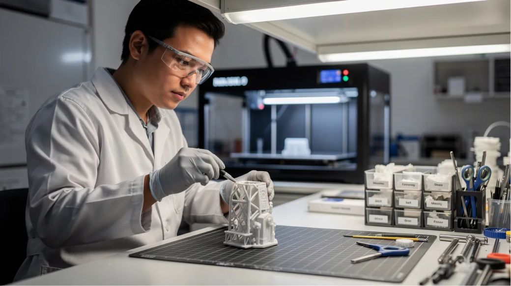
FDM parts often require post-processing for smoother finishes. Fortunately, straightforward techniques can deliver professional results.
- Mechanical finishing: Trim supports with flush cutters, sand progressively from 120 to 600+ grit, fill gaps with automotive body filler, then prime and paint
- Chemical/thermal smoothing: Acetone vapour smoothing for ABS produces a smooth finish; clear epoxy coatings seal and strengthen surfaces
- Functional steps: Press heat-set threaded inserts into PLA or PETG for durable screw joints; bond multi-part assemblies with cyanoacrylate or epoxy
- Example workflow: A raw ABS prototype goes through support removal → 120-grit sanding → filler application → 400-grit sanding → primer → two coats of spray paint to become a presentation-ready model
Parts that require post-processing should have that time factored into project schedules from the start.
Health, Safety, and Environmental Considerations
FDM is relatively safe when used correctly, but there are real risks to manage.
- Emissions: ABS and similar materials release styrene and other VOCs. All thermoplastics emit ultrafine particles that affect indoor air quality. Print in well-ventilated rooms or use enclosures with HEPA and activated carbon filtration.
- Thermal safety: Nozzles exceed 200 °C and heated beds reach 110 °C. Avoid contact during operation, turn off power before maintenance, and supervise long prints or use monitoring systems to reduce fire risk.
- Environmental impact: Failed prints and supports create plastic waste. PLA is biodegradable, and recycled PETG filaments are increasingly available. Community recycling initiatives for spent filament and scrap parts are growing.
FAQ: Fused Deposition Modeling
How strong are FDM parts compared to injection-molded parts?
FDM parts made from the same base polymer are generally weaker than fully dense injection-molded parts, especially in the z direction due to layer interfaces. However, careful orientation, higher infill (50%+), thicker shells, and carbon fiber composite filaments can deliver strength sufficient for many functional applications. In the xy plane, tensile strength can approach injection-molded values with dense infill and proper temperature control.
Can FDM 3D printing be used for food-safe or medical applications?
Some filaments are marketed as food-safe or biocompatible (PET). PET filament can be food-safe when printed with strict controls on printer cleanliness, nozzle material, and post-processing to ensure a smooth, non-porous surface that minimises bacterial growth.
However, the typical rough and porous surface of FDM prints can harbour bacteria, so additional finishing like sanding or coating is often required. For applications involving direct food contact, using certified food-safe PET materials and validated processes that comply with FDA or ISO 10993 standards is essential to ensure safety, but actual safety depends on printer cleanliness, nozzle material, and post-processing.
What is the typical lifespan of FDM-printed end-use parts?
Lifespan depends heavily on material choice, environment, and loading. Indoor PLA parts under light mechanical loads may last 3–5+ years. Outdoor or high-temperature applications typically require PETG, ASA, nylon, or polycarbonate to avoid UV degradation and creep. PEEK and PEI parts in controlled environments can last decades.
Can I print moving mechanisms or assemblies in one piece with FDM?
Yes - hinges, joints, and interlocking chains can be printed in a single build by designing clearances of 0.3–0.5 mm or more between moving surfaces. Success depends on printer calibration, orientation, and careful support removal afterwards. Material choice affects wear: nylon and PETG outperform PLA for repeated motion.
How do I choose between FDM and resin 3D printing for my project?
FDM is usually better for larger, mechanically robust thermoplastic parts and iterative prototyping where material properties matter. Resin printers (SLA/DLP) are preferred for very small, highly detailed components, dental models, jewellery casting patterns, or applications where surface finish and fine detail are critical. FDM wins on material variety and part toughness; resin wins on resolution and smooth finish.
Are you on the hunt for the best large print 3D printer? This article delves into a comprehensive comparison of top models, examining their key features and highlighting the benefits of large format 3D printing.

.svg)